


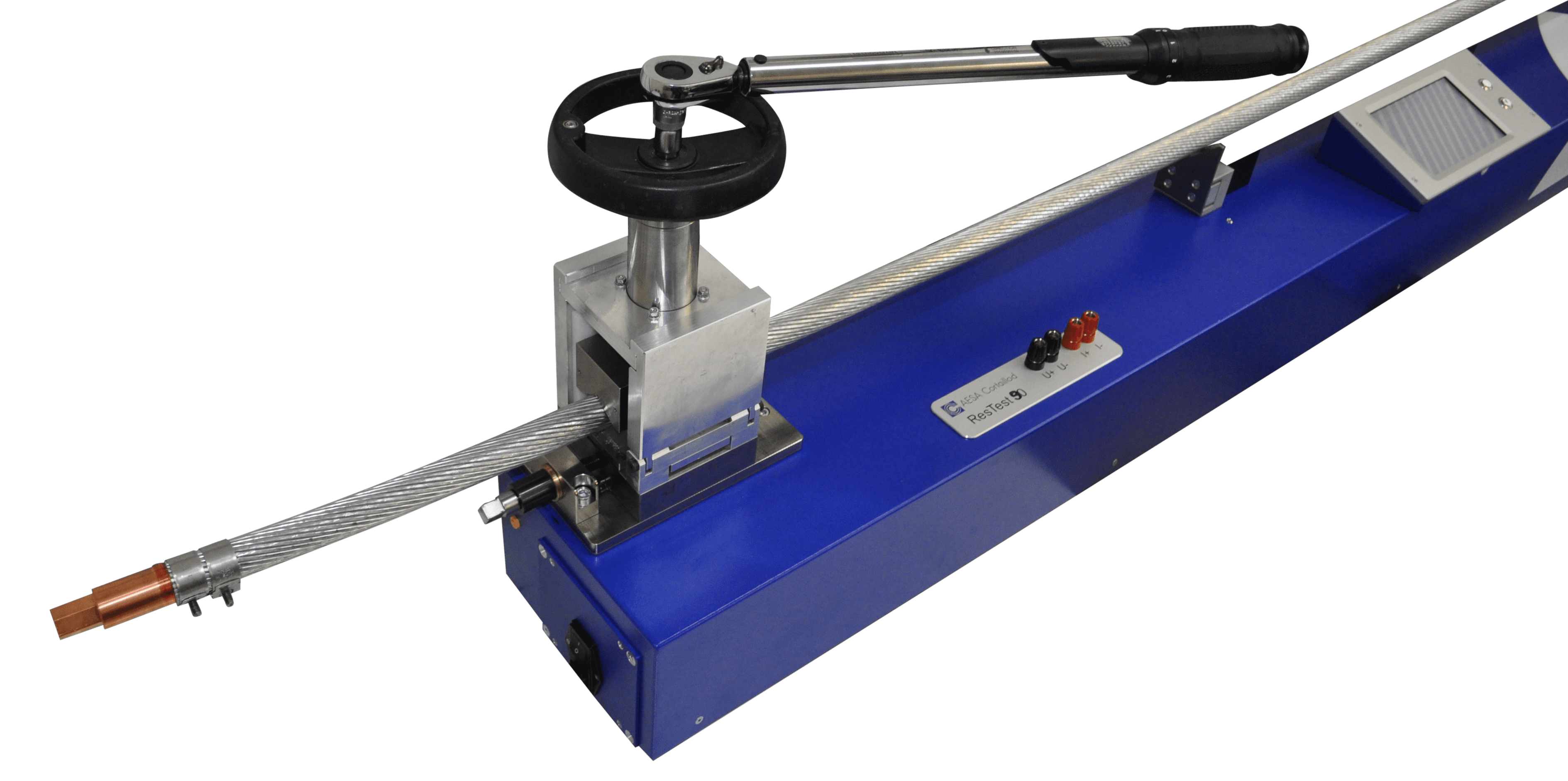
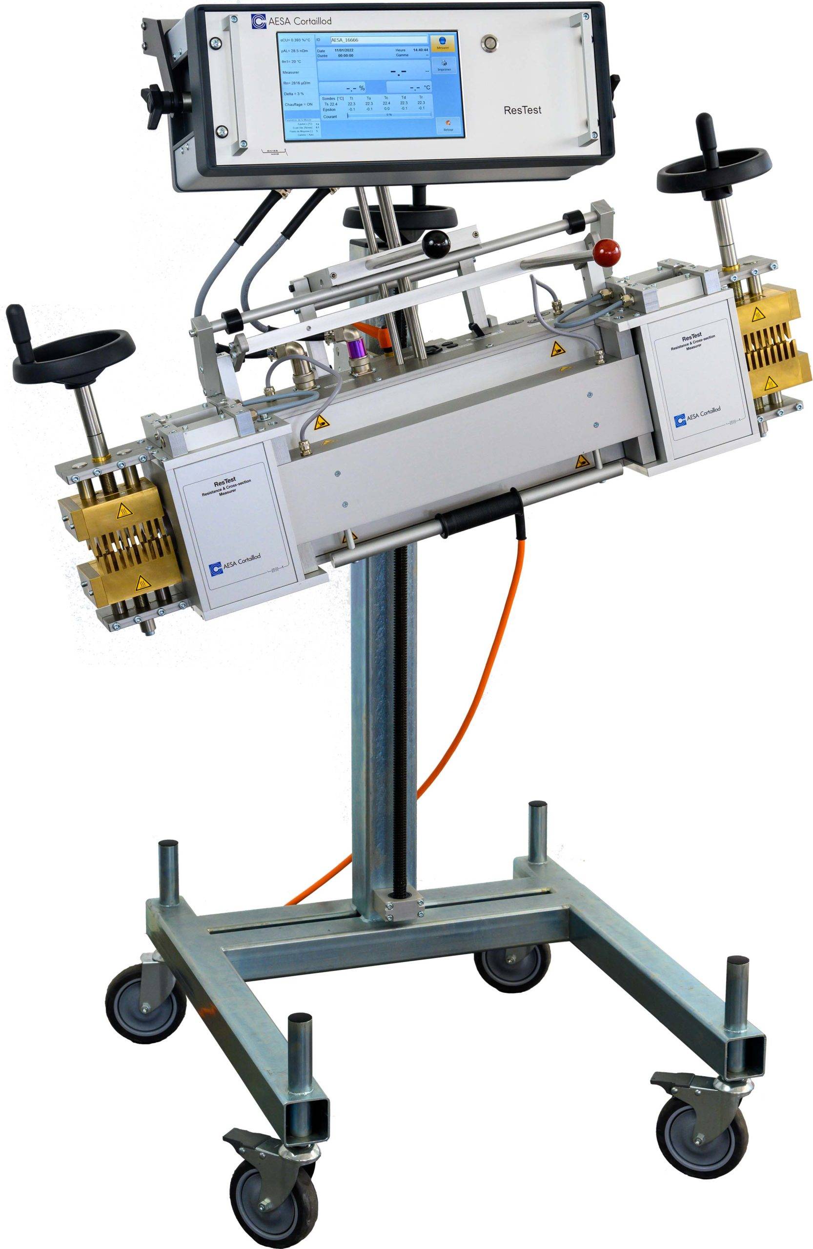
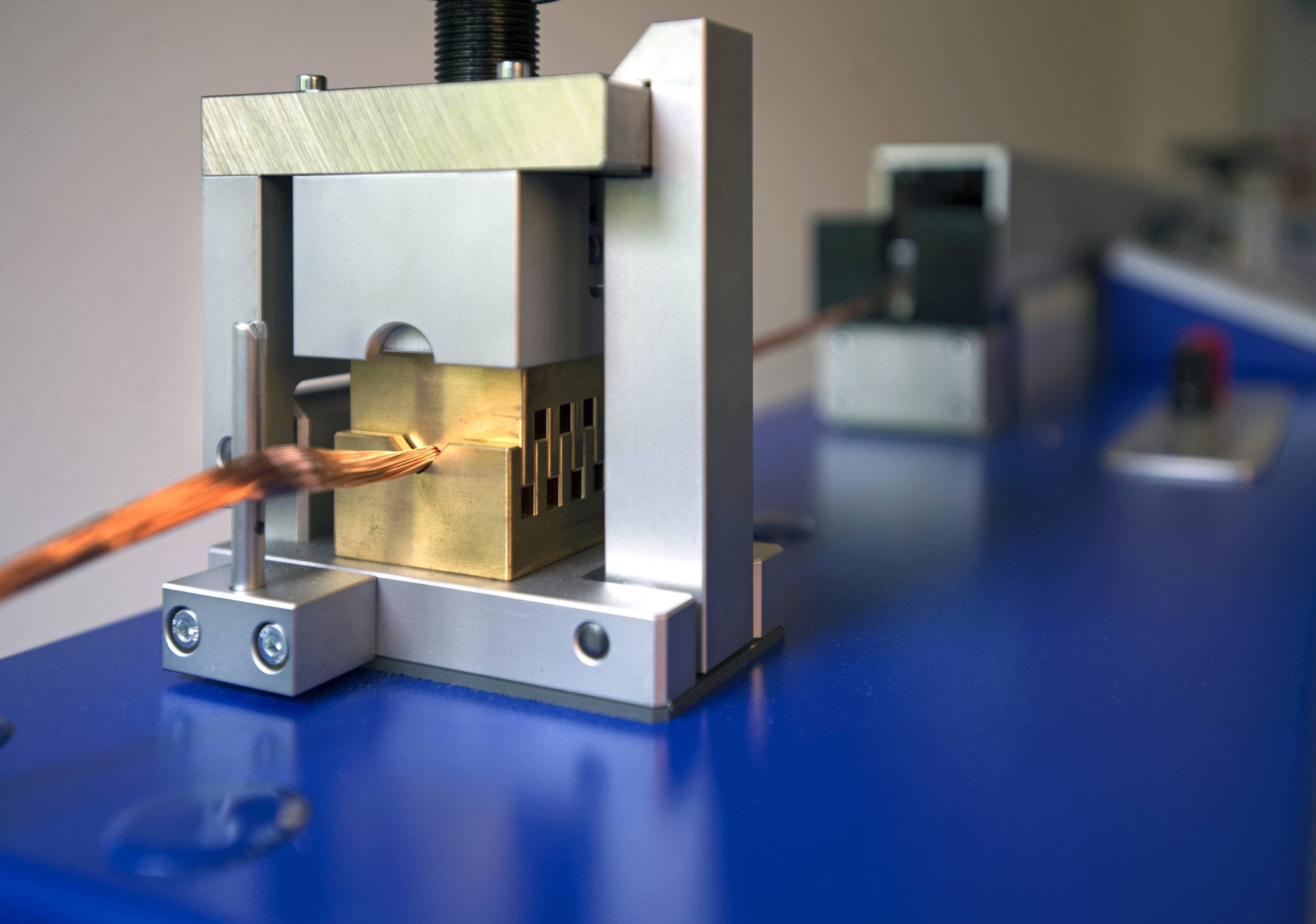
ResTest 90
Conductors up to 1,000 mm2
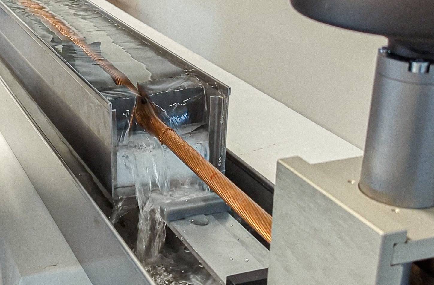
ResTest 95 WaterBath
NEW – cool your conductor fast!
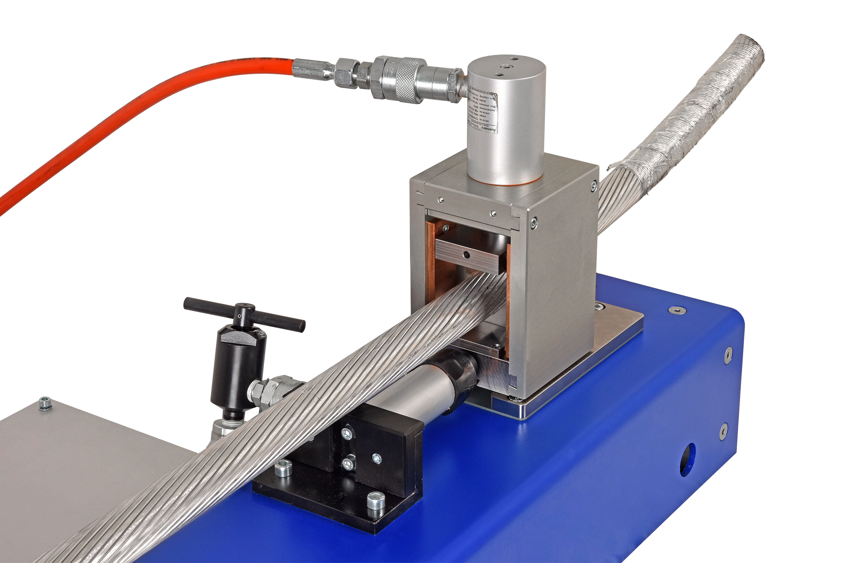
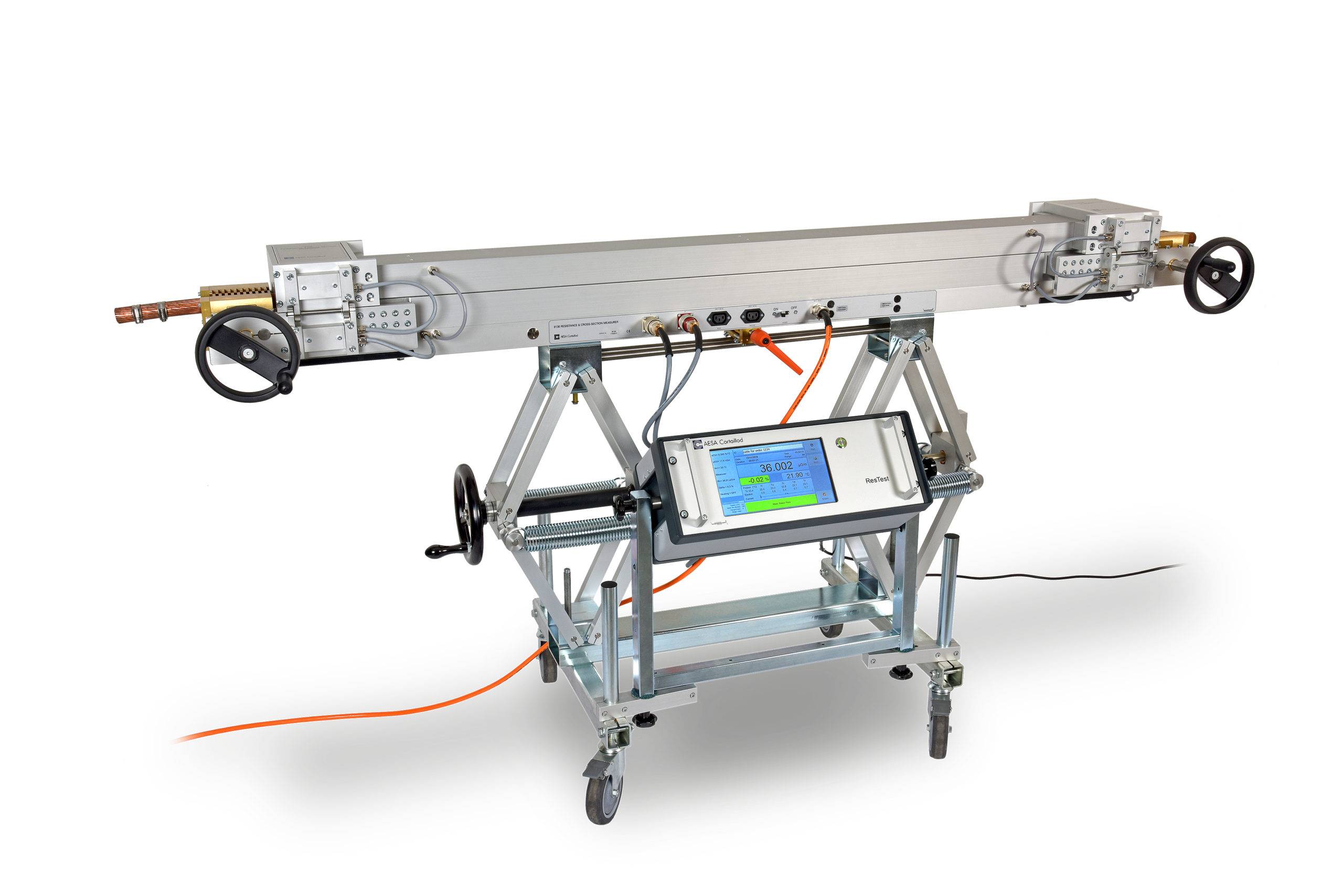
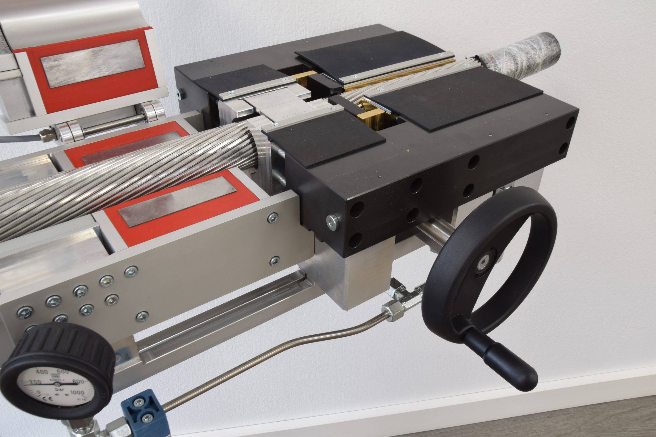
ResTest 210
Conductors up to 4,000 mm2
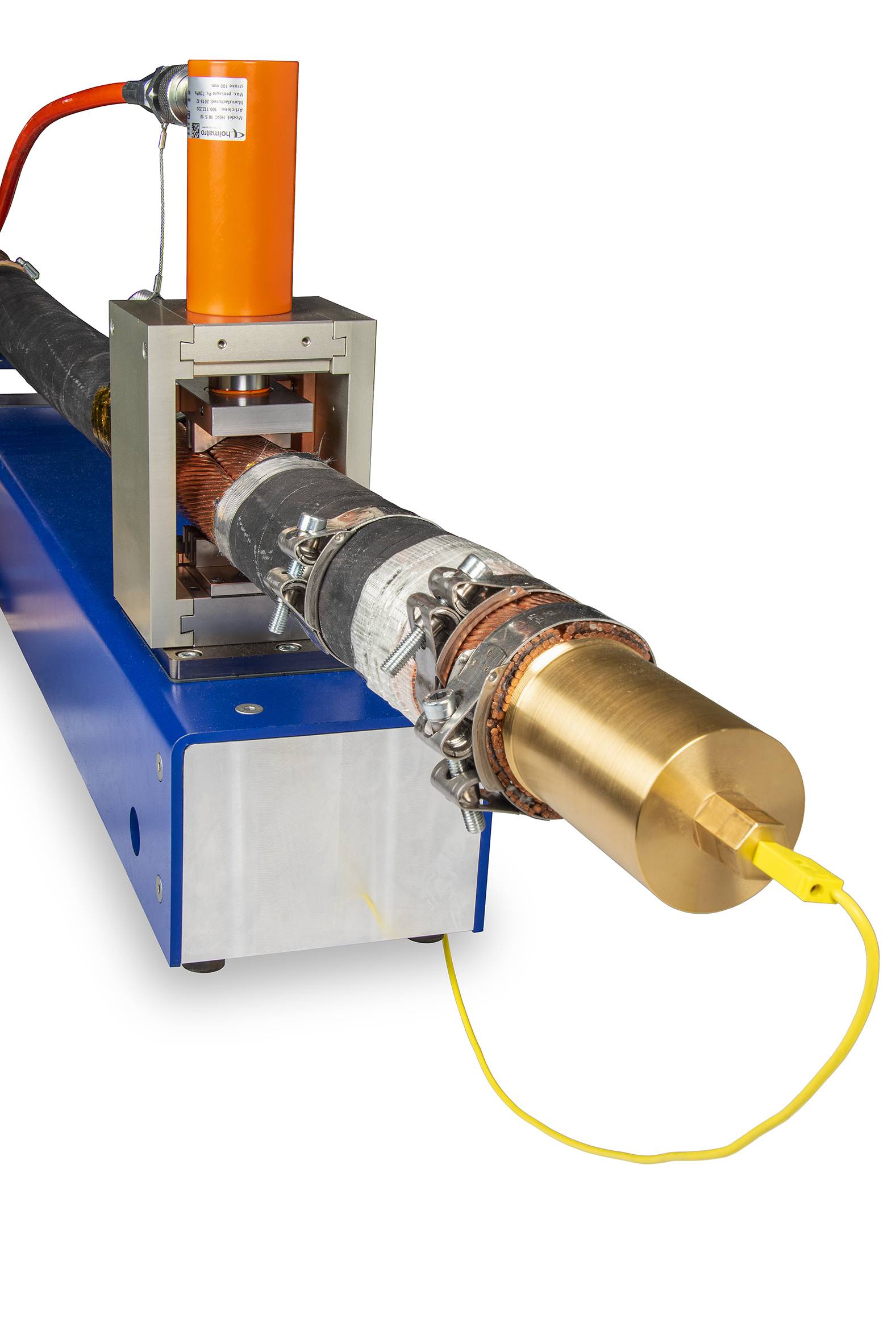
Axial Injection
Increasing accuracy
ResTest 8134
On-the-line for copper conductors
ResTest 8135
On-the-line for aluminium & copper
ResTest 8136
The short version
DC Linear Resistance
Cable Testing Laboratory
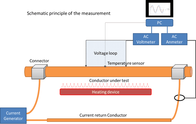
AC Linear Resistance
Cable Testing Laboratory